BetaFPV ExpressLRS SuperP 14Ch Diversity RX
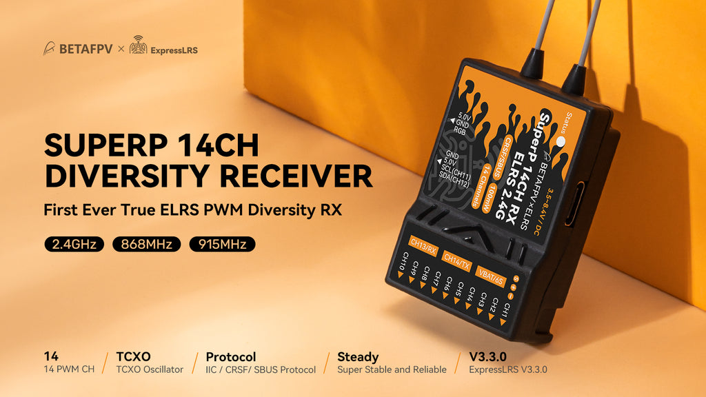
Being the first to market! SuperP 14CH Diversity Receiver has been designed not only for long-range flying, aerial photography but also suitable for the application of fixed-wing, helicopters, RC cars, boats and etc. It has TCXO oscillator, two antennas, dual receiver chains, and Plug-N-Play ports, and adds more features, which support 14 channels for the external barometer, RGB light strip, and other external sensors that are currently under development. This 2.4GHz RX checks all the boxes of reliability for long-range flying, aerial photography, or FPV freestyle. With this receiver, users are able to get a more stable and reliable experience on RC models.
Features
- Featuring 14 PWM channels, this receiver is suitable for different applications. It can drive up to 14 servos, allowing for more complex and precise control. In addition, an external sensor such as a barometer, current sensor, etc, is also supported.
- A true diversity receiver with two complete RF receiver chains (referring to dual SX1280/SX1281 or dual SX1276), based on the latest official ExprssLRS. It comes with ExpressLRS V3.3 firmware.
- Built in a TCXO (temperature-compensated crystal oscillator), it is shared by two RF chips for a super accurate clock source. It can withstand extreme temperatures with no fear of heat and cold, continuously outputting accurate frequency for long-range flight.
- Two antennas will create an omnidirectional signal for good signal transmission. Placing the antenna separately and vertically to get a better signal is recommended.
- With the support of the failsafe function, it is capable of protecting RC models from being out of control.
- Reserving a Type-C USB port, it is convenient for pilots to flash the firmware. The plug-and-play design makes it very easy and friendly to use
Specifications
- Item: BETAFPV SuperP 14CH Diversity Receiver | ELRS 2.4GHz
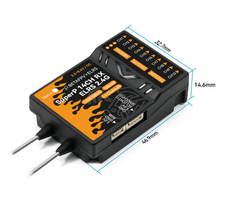
- MCU: ESP32 Pico D4 + 2*SX1280/SX1281 + 2*AT2401C (2.4GHz)
- Telemetry Power: 20dBm/100mW (2.4GHz)
- Frequency Bands: 2.4GHz ISM
- Rated Current: 180mA@5V (2.4GHz)
- Weight: 15.5g (2.4GHz)
- Default Firmware Version: ExpressLRS V3.3.0
- Serial Output Protocol: PWM, CRSF or SBUS
- Antenna: 2* IPEX MHF 1 Antenna
- Size: 46.9mm*32.7mm*14.6mm
- Voltage Detector Range: 1~6S
- Input Voltage: 3.5V~8.4V DC
- PWM Channel: 14 Channels
- Adapted RC Model Type: Multirotors, Fixed-wing aircraft, Helicopters, RC Cars, RC Boats and etc.
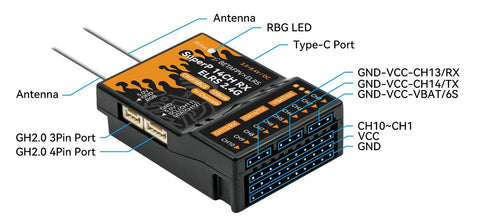
Based on BETAFPV SuperD True Diversity Receiver and Micro Receiver, the SuperP 14CH Diversity Receiver takes the good features of them. For example, 14 PWM channels, two antennas, dual receiver chains, TCXO oscillator, etc. Besides, it has an I2C serial port for more external sensors such as a barometer, and a 3-pin port is reserved for RGB light strip. With the combination of the good points, SuperP RX ensures stability and reliability for users.
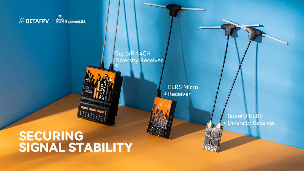
The ExpressLRS receiver protocol can be widely used for more models such as multi-rotors, fixed-wing planes, helicopters, RC cars, RC Boats and etc. The two antennas and dual receiver chains design greatly fulfill the requirements for long-range flying and aerial photography.

It is recommended to place the antenna separately and vertically as far as possible for a better signal.

Know More About the TCXO
SuperP 14CH Diversity Receiver is built-in a TCXO (temperature compensated crystal oscillator), which is shared by two RF chips for a super accurate clock source. The true diversity receiver including two RF chips and PA+LNA will generate a large amount of heat when working. With the high-quality TCXO, it can withstand extreme temperatures with no fear of heat and cold, continuously outputting accurate frequency for long-range flight.

-
RGB status indication for SuperP 14CH Diversity Receiver is shown below.
RGB Color Status Description Rainbow Fade effect Power on Green Slow flash WIFI upgrading mode Red Quick flash No RF chip detected Orange Double flash Binding mode Orange Triple flash Connected, but mismatched model-match configuration Orange Slow flash Waiting for connection Solid on Connected and color indicates packet rate The below picture shows the RGB light color for the 2.4GHz version corresponding to the packet rate.

Note: F1000 and F500 are packet rates in FLRC mode, providing faster modulation and lower latency, but at the same time having shorter reception distance than normal Lora mode. This mode is great for racers.
D500 and D250 are packet rates in DVDA (Deja Vu Diversity Aid) mode. This mode works at the F1000 data packet rate of FLRC mode, providing better link connection in the case of complex interference by sending the same data packet multiple times. D500 and D250 indicate that the same data packet is sent twice and four times respectively.
100Hz Full is the mode that can achieve 16-channel full resolution output at the 200Hz packet rates of Lora mode. Its receiving distance is equivalent to 200Hz.
Port Configuration
Enter the configuration page via WiFi mode.
- Power on the receiver and wait for 60 seconds without binding to any transmitted equipment;
- Once the RGB indicator is in slow green flashing, the receiver's WiFi has been activated;
- Connect WiFi via cellphone or PC (WiFi name: ExpressLRS RX, password: ExpressLRS) ;
- Open the website address: http://10.0.0.1/hardware.html
On the configuration page, users can set the PWM pin, CRSF pin, I2C pin, etc. The pin number corresponds to specified channels. You can refer to the chip I/O function table.
Note: Please do not modify other function pins.
Pin 13 15 2 0 4 9 10 5 Main CH1 CH2 CH3 CH4 CH5 CH6 CH7 CH8 Second Pin 18 23 19 22 3 1 21 36 Main CH9 CH10 CH11 CH12 CH13 CH14 RGB VBAT Second SCL SDA RX TX Third SBUS Note: VBAT is the battery voltage detection port, which supports 1~6S battery voltage detection.
When the RX is configured to use CRSF output, CH13 becomes RX and CH14 becomes TX.
When the RX is configured to use SBUS output, CH13 has no output, and CH14 becomes SBUS.
The CH11 and CH12 of the receiver have been configured as I2C serial ports by factory default. At this time, CH13 becomes CH11, and CH14 becomes CH12.
For example, I2C communication serial port settings are as follows:
- Delete 19 and 22 in the PWM output pin

- Put 19 and 22 into the SCL and SDA pin of the I2C

- Click "SAVE TARGET CONFIGURATION" to complete the setting of the I2C communication serial port
Note: The CH11 and CH12 of the receiver have been configured as I2C serial ports by factory default. Then CH13 becomes CH11, and CH14 becomes CH12.
Binding Procedure
The default firmware of the SuperP 14CH Diversity Receiver uses the ExpressLRS V3.3.0 protocol and has no preset binding phrase. Therefore, the firmware version of the transmitter module must be ExpressLRS V3.0.0 or later versions. Both the receiver and transmitter module should not have any binding phrase.
- Power on and off the receiver 3 times, each step pausing 2 seconds to enter binding mode;
- When the indicator starts fast blink with orange twice, the receiving is at binding mode;
- Enter the radio or transmitter module's binding mode to bind with the receiver; if the Indicator has turned solid, it indicates that the device has been bound successfully.
Note: After the device has been successfully bound, the receiver will record the device, and future binding will be automatic. There would be no need to go through the binding process again.
Failsafe and Channel Output Settings
The setting method is as follows:
- After the receiver is powered on, wait for 60 seconds without connecting the remote control
- The RGB indicator enters the green slow flashing state, and the receiver automatically turns on WiFi (WiFi name: ExpressLRS RX, WiFi password: ExpressLRS)
- Use a mobile phone or computer to connect to WiFi, and log in to http://10.0.0.1 with a browser to find the model page
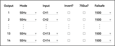
Failsafe settings are as follows: The output value of the servo can be obtained when the out-of-control protection value is inputted and the system goes out of control.
Note: Do not click "Reverse". If you click the "750us", the failsafe value needs to be halved. When the failsafe value is greater than 1500, the mode will automatically switch to "On/Off" mode.
Channel output settings are as follows: Select the desired mode from the dropdown menu of the mode, and the following are descriptions of all output modes.
- 50-400Hz: output PWM signal frequency
- 10KHzDuty: used to directly drive micro-motors
- ON/OFF: output high-level or low level
- Serial TX/RX: Serial communication port
CRSF/SBUS output settings are specified below:
- Set the mode of channel 13 to serial RX or set the mode of channel 14 to Serial TX

- Select the serial port protocol in Serial Protocol, and click "SAVE" to save the settings

- Set the baud rate on the options page (the SBUS serial protocol cannot set the baud rate)

- Click "SAVE&REBOOT" to complete the setting of the CRSF/SBUS output
Note: When the receiver is configured to use CRSF output, CH13 becomes RX and CH14 becomes TX; When the receiver is configured to use SBUS output, CH13 has no output, and CH14 becomes SBUS.
FAQ
- BETAFPV SuperP 14CH Diversity Receiver user manual for download.
- Download the Firmware for SuperP ELRS 2.4GHz/915MHz/868MHz Diversity Receiver.
- This receiver can only accept power sources 3.5~8.4V, which meets the requirements of most servo applications. Therefore, a 2S battery or above needs to be converted to 5V using a BEC before being connected to the receiver.
- The Y-cable is used to avoid the power port being occupied by the power plug. One end of the cable connects to the servo while the other end connects to the power source.
- Method of the VBat voltage adjustment.
- Video for SuperP 14CH Diversity Receiver.
PACKAGE CONTENTS
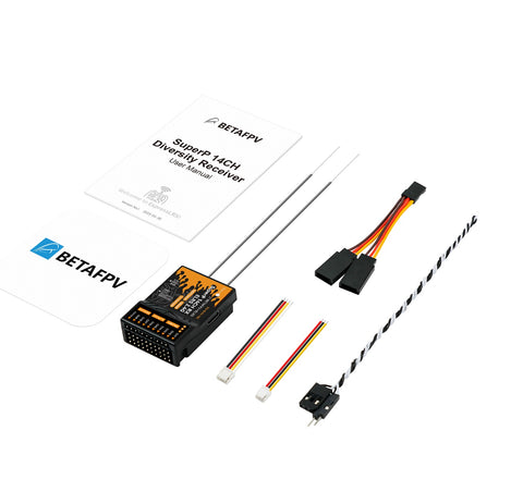
- 1 * SuperP 14CH Diversity Receiver (2.4GHz)
- 2 * 150mm Monopole Antenna (2.4GHz)
- 1 * GH2.0 3-Pin Cable
- 1 * GH2.0 4-Pin Cable
- 1 * Y Splitter Cable for Servo
- 1 * Voltage Test Cable
- 1 * User Manual
- Receiver Type:
- ExpressLRS


